Codevisionavr Serial
Posted By admin On 21/12/17Thanks a lot again, and probably you are right. Unfortunately I have deleted the folder where were the modified source and the compiled file. I only replaced/added '0' and '0A', where I was getting error after compile (read datasheet for the variable/register and added '0'/'0A'). But did nothing with the Rx pin (PORTD.0 ->PORTD.2). If I do it again, I shall remember this INT0 matter. Sorry, can't test all these right now due to some other works. Also planned to do it on Arduino.
I like to use various Arduino boards for AVR development. What I do not like are the Arduino libraries. They are often just wrappers around libc functions or rewrites. CodeVisionAVR V3 is designed to be used both in its own IDE and also as an Extension in Atmel Studio 6.1 or later version. It is compatible with Windows® XP, Vista.
I am grateful to you. I also believe your information will help others. Take care and best regards.

In this tutorial we are going to establish a serial communication between two ATMEGA8 microcontrollers. The communication established here is UART (Universal Asynchronous Receiver Transmitter) type. By this serial communication data can be shared between two microcontrollers, which is required in various embedded systems. Components Required Hardware: ATMEGA8 (2 pieces), power supply (5v), AVR-ISP PROGRAMMER, 100uF capacitor (connected across power supply), 1KΩ resistor (two pieces), LED, Button. Software: Atmel studio 6. School Days Hq Eng here. 1, progisp or flash magic.
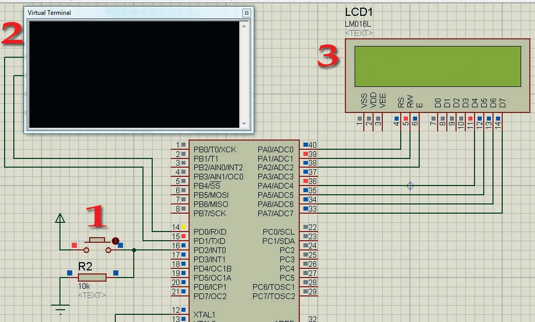
Circuit Diagram & Explanation Let us understand the serial communication in AVR microcontrollers. Here ATMEGA sends data to the other ATMEGA in serial. Uefa Champions League Font. It has other mode of communication but for easy communication we are choosing. The RS232 pin of first ATMEGA8 is connected to RXD pin of second ATMEGA8. The data communication established is programmed to have: • Eight data bits • Two stop bits • No parity check bit • Baud rate of 2400 BPS(Bits Per Second) • Asynchronous communication (No clock share between two ATMEGA8) So we have two set registers for two ATMEGA8 differently, where one acts as TRANSMITTER and other acts as RECEIVER.
Now for the RS232 interfacing between two ATmega microcontrollers, the following features must be satisfied for the TRANSMITTER and RECEIVER: 1. The TXD pin (data receiving feature) of first controller must be enabled for TRANSMITTER and RXD pin of second controller must be enabled for RECEIVER. Since the communication is serial we need to know whenever the data byte is received, so that we can stop the program until complete byte is received. This is done by enabling a data receive complete interrupt. DATA is transmitted and received to controller in 8bit mode.
So two characters will be sent to the controller at a time. There are no parity bits, one stop bit in the data sent by the module. The above features are set in the controller registers; we are going to discuss them briefly, DARK GREY (UDRE): (TRASMITTER SIDE) This bit not set during startup but it is used during working to check whether transmitter is ready to transmit or not.